Non-Isolated POL Converters sit close to the load, where voltage accuracy, transient response, heat, and board space directly affect system reliability. In servers, telecom equipment, industrial controls, and automotive electronics, a poor selection can create visible ripple, hot inductors, or unstable startup behavior. Small details matter.
The Lawrence Berkeley National Laboratory’s 2024 United States Data Center Energy Usage Report estimates that U.S. data centers consumed about 176 terawatt-hours of electricity in 2023. It projects consumption could reach 325–580 terawatt-hours by 2028. That pressure makes efficient, dense power delivery increasingly important. Alex Lidow, CEO of Efficient Power Conversion, has stated, “Power conversion is the enabling technology for the electrification of everything.” His observation applies directly to POL design, where every millivolt and milliwatt can influence system performance.
Choosing a converter is not merely a current-rating exercise. Engineers must examine input transients, switching frequency, thermal impedance, control-loop behavior, output capacitance, EMI, and protection features. Datasheet efficiency may also change sharply at light loads. That is easy to miss. The following seven tips provide a practical framework for comparing Non-Isolated POL Converters, from reading realistic efficiency curves to checking layout guidance and long-term supplier support. Some recommendations may seem obvious, yet field failures often begin with overlooked assumptions. No checklist removes every risk. It does, however, make weak decisions easier to identify before prototypes reach the bench.
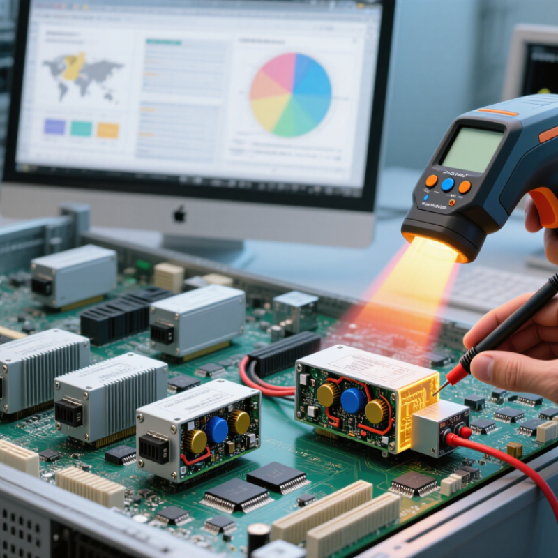
Before comparing non-isolated POL converters, define the job the circuit must perform. A POL converter steps a local voltage down near the load. It normally shares ground with the input source and system electronics. That shared path simplifies wiring but increases the importance of grounding, noise, and layout. The seven buying checks should begin here.
Record the input range, target output, load current, transient demand, and allowed ripple. Then match the converter to real operating conditions, not only the nominal voltage. A processor may need a steady 1.0 V rail while its current changes sharply within microseconds. The converter must respond without excessive overshoot or a reset. Small details matter. Check switching frequency, feedback tolerance, enable behavior, and protection features. Current ratings can look impressive, yet thermal limits may reduce usable output.
Efficiency also defines the role. A compact board with poor airflow may need lower heat generation more than peak current. Review derating curves, thermal resistance, and recommended copper area. In one board review, a converter met the electrical target but ran hot because the layout copied a reference circuit without copying its copper pattern. That was an expensive assumption. Use the datasheet as a technical starting point, then verify performance on your own board. Measure ripple with a careful probe setup, test startup, and apply fast load steps. Leave margin. A converter that works only under ideal bench conditions is not a reliable purchase.
This example uses common board-level power rails supplied from a 12 V intermediate bus. Output power is calculated as VOUT × IOUT, while the ideal buck duty cycle is calculated as VOUT ÷ VIN. Use these requirements to evaluate voltage range, current capability, thermal performance, transient response, and efficiency before selecting a non-isolated POL converter.
Buying a non-isolated POL converter requires more than matching a nominal voltage. The input rail may be noisy, variable, or briefly higher during startup. Check the complete input range, not only the typical value. A 12 V system, for example, may actually operate between 9 V and 14.4 V.
Tip 1: Compare the converter’s input limits with real measurements from your board. Leave headroom for surges and wiring variation. I have seen designs pass bench tests but reset when a motor started nearby. That detail is easy to miss. Also inspect undervoltage lockout and switching frequency, because both affect system behavior.
Tip 2: Match the output specification to the load’s actual needs. A processor may require 1.1 V with tight tolerance, while memory or sensors may accept a wider range. Check ripple, transient response, and voltage accuracy under changing loads. The advertised output current is not always available continuously. Temperature matters. Review derating curves and airflow requirements before selecting the part.
Tip 3: Compare current ratings using worst-case calculations, not average consumption. Include startup current, sleep-to-active transitions, and future firmware changes. A converter rated for 3 A may run hot at 2.8 A in a compact enclosure. Measure the inductor and nearby components during testing. My own estimates have been optimistic before, especially when several loads switched together. That mistake deserves a second check.
Tip 1: Check efficiency across the real load range, not only the headline value. A converter may reach 95% efficiency at full load, yet perform poorly at light load. Measure input current at standby, half load, and peak load. Use the intended input voltage. Small differences become meaningful in dense systems. I once trusted a typical curve too quickly. That choice created unexpected heat during low-load operation.
Tip 2: Treat thermal performance as a design limit. Review junction temperature, thermal resistance, derating guidance, and airflow conditions. A compact converter can feel cool on the bench but overheat inside a sealed enclosure. Place temperature sensors near the package and output capacitors. Allow copper beneath the converter to spread heat. Do not assume a larger heatsink solves every problem. Poor layout can still trap heat.
Tip 3: Compare power density with stability and serviceability. Higher watts per cubic centimeter can reduce board area, but it may increase switching noise and thermal stress. Examine transient response, ripple, minimum load, and recommended external components. Keep high-current paths short and wide. Test sudden load changes with an oscilloscope, not just a multimeter. Leave some margin. A design that barely meets its rating may fail after dust, aging, or warmer ambient conditions.
7 Tips for Buying Non-Isolated POL Converters
A non-isolated POL converter sits close to the processor, memory, or FPGA. Small control mistakes can become expensive board failures. Check the control loop before checking the price. A converter should offer stable voltage regulation during rapid load changes. Look for remote sensing, programmable soft-start, power-good signaling, and adjustable switching frequency. Current-mode control is useful, but its compensation network still needs careful review.
Protection functions deserve equal attention. Confirm cycle-by-cycle overcurrent protection, short-circuit behavior, thermal shutdown, input undervoltage lockout, and output overvoltage protection. Ask what happens after a fault. Does the converter latch off, hiccup, or restart automatically? That detail matters near sensitive processors. The Uptime Institute’s 2024 Annual Outage Analysis reported that more than half of surveyed outages exceeded $100,000 in cost. A small protection gap can therefore create a large system problem.
Reliability also depends on layout, temperature, and electrical stress. Review derating curves, component lifetimes, and qualification data under realistic airflow conditions. JEDEC’s JESD47 qualification framework is a useful reference for semiconductor reliability testing, but qualification is not the same as field reliability. I have seen clean laboratory results fail after dust buildup and repeated thermal cycling. The overlooked detail is often the feedback trace. Keep it short, quiet, and away from the switching node. Then test startup, shutdown, overload, and recovery at the hottest expected condition. The first test may pass. The second one matters more.
Buying a non-isolated point-of-load (POL) converter starts with the board, not the catalog. Measure available height, copper area, airflow, and distance to the load. A 12 mm package may fit the schematic but collide with a shield or heatsink. Sketch the power path on the actual PCB. Keep input and output loops short. Reserve space for capacitors, test points, and thermal spreading. Small details matter.
Compatibility requires more than matching voltage. Check the input range, output accuracy, transient response, switching frequency, current-sharing behavior, and protection thresholds. Compare these values with the processor’s startup profile and worst-case load step. Review the recommended layout, then test it with your own stack-up and copper thickness. A converter can pass bench tests yet fail after a long trace adds noise. I have seen this happen. Thermal results also change inside an enclosure, especially near memory devices or hot regulators. Leave margin because nominal ratings are not operating guarantees.
Supplier support should be measurable. Ask for complete datasheets, SPICE models, reference layouts, loss curves, lifecycle information, and documented change notices. Request answers from an applications engineer, not only a sales channel. Confirm sample availability, production capacity, and failure-analysis procedures before approval. Good support shortens debugging. It does not replace verification. Keep records of every revision and test condition. One overlooked capacitor value can waste days. I still review that assumption twice.
| Tip | Verification Dimension | Typical Engineering Data | What to Check Before Purchase | Buying Decision Guide |
|---|---|---|---|---|
| 1 | Input and Output Voltage Compatibility | Common POL input ranges are approximately 4.5–5.5 V, 8–14 V, or 18–36 V. Output rails commonly range from about 0.6–5 V, depending on the device. | Confirm the full input-voltage range, start-up voltage, under-voltage lockout, output adjustment range, remote-sense limits, and output-voltage tolerance. | Select a converter whose operating range covers normal input variation, transients, and the required regulated output without operating at the limits. |
| 2 | Load Current and Transient Performance | POL converters are available from sub-ampere ratings to more than 50 A per module. Fast digital loads may create load steps of several amperes within microseconds. | Review continuous current, peak current duration, load-step test conditions, recovery time, overshoot, undershoot, and required output-capacitor values. | Choose sufficient current margin, typically at least 20–30% above the expected continuous load, and validate the worst-case transient profile. |
| 3 | PCB Layout and Thermal Requirements | High-current switching paths should be short and wide. Thermal performance depends on copper area, layer structure, airflow, ambient temperature, and package thermal resistance. | Check recommended PCB placement, minimum copper area, exposed-pad requirements, via guidance, keep-out zones, switching-node routing, and maximum case or junction temperature. | Reject products that cannot fit the available board area or meet thermal limits under the actual enclosure and airflow conditions. |
| 4 | Efficiency, Heat, and Operating Frequency | Many synchronous POL designs achieve roughly 85–95% efficiency at favorable input, output, and load conditions. Switching frequencies commonly range from several hundred kilohertz to a few megahertz. | Compare efficiency curves at the intended load, switching frequency, no-load consumption, temperature rise, and electromagnetic-interference test results. | Use the complete efficiency curve rather than a single headline value, especially when the converter operates at light load or near maximum current. |
| 5 | Output Ripple and Noise Control | Output ripple is affected by switching frequency, inductor selection, capacitor impedance, layout parasitics, load current, and measurement bandwidth. | Verify ripple specifications with stated bandwidth, probe method, capacitor type, capacitor quantity, ESR range, and operating conditions. | For sensitive processors, data converters, or RF circuits, consider a post-regulation filter or secondary low-noise regulator if the POL output alone is insufficient. |
| 6 | Protection and System Compatibility | Common protection functions include over-current protection, short-circuit protection, over-temperature protection, input under-voltage lockout, and output over-voltage protection. | Confirm latch-off or hiccup behavior, soft-start timing, power-good thresholds, enable-pin logic, start-up into pre-biased loads, reverse-current behavior, and fault recovery. | Match the protection response to the system requirement; automatic restart and latch-off behavior can have very different safety implications. |
| 7 | Documentation, Qualification, and Supplier Support | A production-ready power solution should include electrical specifications, recommended layout, bill of materials guidance, reliability information, qualification data, and lifecycle details. | Request a complete datasheet, evaluation-board files, SPICE or simulation models when available, test reports, change-notification policy, lead-time information, and technical support contacts. | Prefer a supplier that can support schematic review, layout review, sample testing, failure analysis, and long-term production planning. |
| Practical checklist: Validate the converter with the final PCB, specified capacitors and inductors, actual input transients, expected load steps, enclosure temperature, and required electromagnetic-compatibility conditions. Electrical values are typical engineering ranges and must be confirmed against the selected device documentation. | ||||
Record the input range, target output, load current, transient demand, and allowed ripple. Test real conditions, not only nominal voltage. Leave margin.
A nominal 12 V rail may vary from 9 V to 14.4 V. Check startup surges, wiring drops, noise, and undervoltage lockout. Bench values can mislead.
Check voltage accuracy, ripple, transient response, and changing load behavior. A processor may need a steady 1.0 V rail during microsecond current changes.
No. Thermal limits, airflow, and enclosure temperature can reduce continuous output. A 3 A converter may run hot near 2.8 A.
Include startup current, sleep-to-active transitions, fast load steps, and possible firmware changes. Several loads may switch together. Average current is not enough.
Keep input and output loops short. Provide suitable copper, capacitors, test points, and thermal spreading. Check package height near shields or heatsinks.
No. Your PCB stack-up, copper thickness, trace length, and enclosure may differ. One copied layout can still run hot or create noise.
Request complete datasheets, models, reference layouts, loss curves, lifecycle details, and change notices. Confirm samples, production capacity, and failure-analysis procedures.
Measure ripple with careful probing, test startup, and apply fast load steps. Monitor the inductor and nearby components. Ideal bench results are not enough.
Choosing the right Non-Isolated POL Converters begins with clearly defining the converter’s role, load requirements, operating environment, and system constraints. Compare the input voltage range, regulated output voltage, rated current, transient response, and scalability to ensure the device can support both normal operation and peak demand. Efficiency should be assessed across the expected load range, while thermal performance and power density must be considered to prevent overheating and make efficient use of available board space.
A thorough evaluation should also include control features, startup behavior, voltage adjustment, monitoring options, and protection against overcurrent, overvoltage, short circuits, and excessive temperature. Confirm that the converter fits the planned PCB layout, grounding strategy, electromagnetic compatibility requirements, and surrounding components. Finally, review documentation quality, testing information, availability, lifecycle stability, and technical support so the selected solution remains reliable and practical throughout product development and long-term operation.